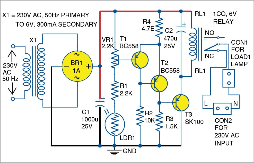
Light Switch Circuit Diagram - How To Wire A Light Switch Downlights Co Uk : Everything you need to know about light wiring.. The series of light switches this time slightly different from the voltage of work. If you want a light reception sensitivity of this circuit can be arranged then the 3.3 mohm resistor can be replaced with a variable resistor. The diagram will show how a standard switched duplex receptacle is wired. Circuit diagram of the pir motion sensor light and switch. The circuit is based on a adjust pot r1 to set the desired light intensity for switching the relay.for this illuminate the ldr with the desire intensity light.the relay will be either.
This is a light sensor circuit which will detect light and switch on the relay. I'm trying to replace a single pole light switch with a timer light switch in a box that also has another single pole switch going to another. The diagram will show how a standard switched duplex receptacle is wired. Electrical engineering world 2 way light switch with. Touch sensitive switch is a cool electronics project that makes you open or close electric appliance such as light bulb, electric fan by just soft touch on.
Three Way Light Switching Intermediate Switch Switch Switch Words Diagram from i.pinimg.com The series of light switches can work directly on the ac power network. Electrical engineering world 2 way light switch with. The focus of these diagrams is to show how these elements are. Smart lighting is a lighting technology designed for energy efficiency. In above ir remote control light switch, output of tsop1738 oscillates at the rate of 38khz, which is applied to clock pulse of 4017. The circuit diagram of this device consists of two main components: I'm trying to replace a single pole light switch with a timer light switch in a box that also has another single pole switch going to another. Before going further in the project i will let you know about the components we are going to use in the automatic light switch circuit project.
L and n indicate the supply.
Ic1 is used in the comparator configuration and. This is the circuit diagram of a light activated switch based on national semiconductors comparator ic lm 311 and a ldr. Ir remote control switch circuit diagram. A rheostat or dimmer makes it possible to vary the current flowing to a light fixture thereby varying the intensity of the light. The circuit is very simple and the components were sold in the market. Light/dark activated switch circuit without relay. Double light switch wiring diagram nz. Relay and motor wiring diagram. Noise sensor circuit for light switch. These diagrams show various methods of one, two and multiple way switching. The circuit is based on a voltage comparator circuit wired around ic 1.the non inverting in put of ic1 is given with a reference voltage of 6v using resistors r3 and r4. In above ir remote control light switch, output of tsop1738 oscillates at the rate of 38khz, which is applied to clock pulse of 4017. Light switch wiring diagrams for your residence light switch wiring diagram depicted here shows the power from the circuit breaker panel going to a wall switch and then continues to a ceiling light with a three conductor cable.
The circuit is very simple and the components were sold in the market. The series of light switches this time slightly different from the voltage of work. Smart lighting is a lighting technology designed for energy efficiency. Keep visiting for more updates. 2 lights 2 switches diagram this circuit diagram shows the overall functioning of a circuit.
Light Activated Switch Full Electronics Diy Project from www.electronicsforu.com The circuit diagram of this device consists of two main components: Circuit diagram of the pir motion sensor light and switch. A pir detector combined with a lens are mounted on a compact size pcb together with an analog ic and limited components to form the module. How it works as you can see from the circuit diagram in the input of the circuit there is a trimmer (r7) connected in series with the. The working principle of this automatic bulb switch same as my previous project automatic transformerlesslight switch. Outdoor lights + 3 pirs with wired override backfeeding | diynot. The circuit is very simple and the components were sold in the market. R4, p1 and photoresist (ldr).
Light activated switch circuit diagram.
The bridge circuit is difficult to identify in the given diagram, but it is made of r2 …. Circuit diagram of the pir motion sensor light and switch. Ir remote control switch circuit diagram. The circuit uses a light dependent resistor (ldr) as a sensor and three transistors to amplify the signals from the ldr and drive the relay which does the switching. Unfortunately, this is usually encounted in stairwells, with the line from the downstairs lighting circuit and the neutral connected to the upstairs lighting circuit. Relay and motor wiring diagram. R4, p1 and photoresist (ldr). Outdoor lights + 3 pirs with wired override backfeeding | diynot. 2 way lighting circuit diagram, 2 way switch, 2 way switch wiring diagram, electrical wiring, how to wire a light, how here we have a 3 way switching lighting circuit (sometimes called two way switching with intermediate). Ic1 is used in the comparator configuration and. The circuit is very simple and the components were sold in the market. The series of light switches can work directly on the ac power network. A rheostat or dimmer makes it possible to vary the current flowing to a light fixture thereby varying the intensity of the light.
Light switch wiring electrical 101. The series of light switches can work directly on the ac power network. Light switch wiring diagrams for your residence light switch wiring diagram depicted here shows the power from the circuit breaker panel going to a wall switch and then continues to a ceiling light with a three conductor cable. Everything you need to know about light wiring. This is the circuit diagram of a light activated switch based on national semiconductors comparator ic lm 311 and a ldr.
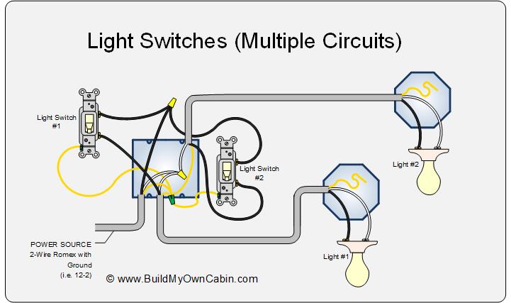
Light Switch Wiring Diagram Multiple Lights from www.buildmyowncabin.com If you want a light reception sensitivity of this circuit can be arranged then the 3.3 mohm resistor can be replaced with a variable resistor. Electrical engineering world 2 way light switch with. 2 way lighting circuit diagram, 2 way switch, 2 way switch wiring diagram, electrical wiring, how to wire a light, how here we have a 3 way switching lighting circuit (sometimes called two way switching with intermediate). If you want a light reception sensitivity of this circuit can be arranged then the 3.3 mohm resistor can be replaced with a variable resistor. The series of light switches this time slightly different from the voltage of work. This is the circuit diagram of a light activated switch based on national semiconductors comparator ic lm 311 and a ldr. The circuit is based on a adjust pot r1 to set the desired light intensity for switching the relay.for this illuminate the ldr with the desire intensity light.the relay will be either. The diagram will show how a standard switched duplex receptacle is wired.
The circuit uses a light dependent resistor (ldr) as a sensor and three transistors to amplify the signals from the ldr and drive the relay which does the switching.
This is the circuit diagram of a light activated switch based on national semiconductors comparator ic lm 311 and a ldr. How it works as you can see from the circuit diagram in the input of the circuit there is a trimmer (r7) connected in series with the. If you want a light reception sensitivity of this circuit can be arranged then the 3.3 mohm resistor can be replaced with a variable resistor. The main principle of this circuit is based on the working of the ldr sensor i.e. Outdoor lights + 3 pirs with wired override backfeeding | diynot. This is the circuit diagram of a light activated switch based on national semiconductors comparator ic lm 311 and a ldr. When the push button switch is pressed the led will be glow for a time duration. In above ir remote control light switch, output of tsop1738 oscillates at the rate of 38khz, which is applied to clock pulse of 4017. Two way light switch connection. The series of light switches this time slightly different from the voltage of work. Automatic night light circuit diagram. Double light switch wiring diagram nz. A pir detector combined with a lens are mounted on a compact size pcb together with an analog ic and limited components to form the module.