Home
› Schematic Diagrams Symbols - Electrical Schematic Symbols Chart Pdf Danada - Photos of some common components are included, but note, the photos are not.
Schematic Diagrams Symbols - Electrical Schematic Symbols Chart Pdf Danada - Photos of some common components are included, but note, the photos are not.
Schematic Diagrams Symbols - Electrical Schematic Symbols Chart Pdf Danada - Photos of some common components are included, but note, the photos are not.. Our circuit diagram symbol library is schematic and includes many icons commonly used by engineers. Wiring diagrams symbols www automanualparts comwiring diagrams symbols auto manual parts wiring diagram pinterest symbols. Below is a list of common symbols you might see in these schematics. In complex diagrams it is often necessary to draw wires crossing even though they are not connected. There is a quite adequate collection of symbol for electrical, electronic circuit.
As you go through various parallax microcontroller tutorials, you will see schematics describing the circuits to be built. There are two different symbols used, either a zigzag line, or a rectangle. Also seen dependcin?g upon the cocu?ntry of origin. Ciircuits, diagrams & symbols includes: All circuit symbols are in standard format and can be used for drawing schematic circuit diagram and the symbols for different electronic devices are shown below.
For Beginners Reading Schematics Circuit Diagrams Part 1 from www.radiomuseum.org Schematic diagrams should be arranged for simplicity and ease of understanding without regard for the actual physical location of any component, only focusing on how they connect the block diagram provides a conceptual idea how a process is completed without regard for electrical symbols or terms. Also seen dependcin?g upon the cocu?ntry of origin. As you go through various parallax microcontroller tutorials, you will see schematics describing the circuits to be built. Circuit layouts and schematic diagrams are a simple and effective way of showing pictorially the electrical. Schematics using international symbols may instead use a featureless rectangle, instead of the squiggles. Circuit symbols are used in circuit diagrams (schematics) to represent electronic components. Below is a list of common symbols you might see in these schematics. In the schematic shown above, the symbol next to the bt represents a battery, the symbol next to the s represents a switch, and the one next to ds represents a display or.
It reveals the components of the circuit as simplified forms and also the power as well as signal links between the devices.
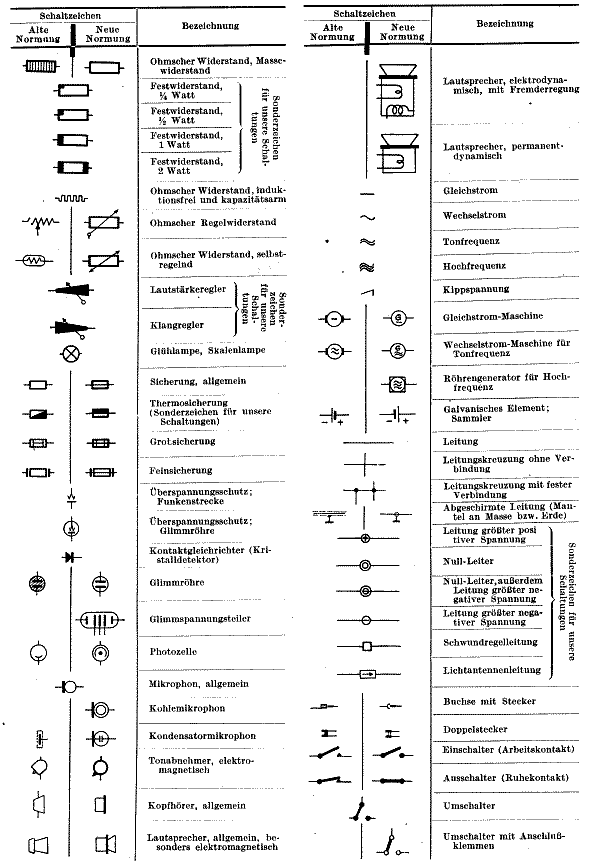
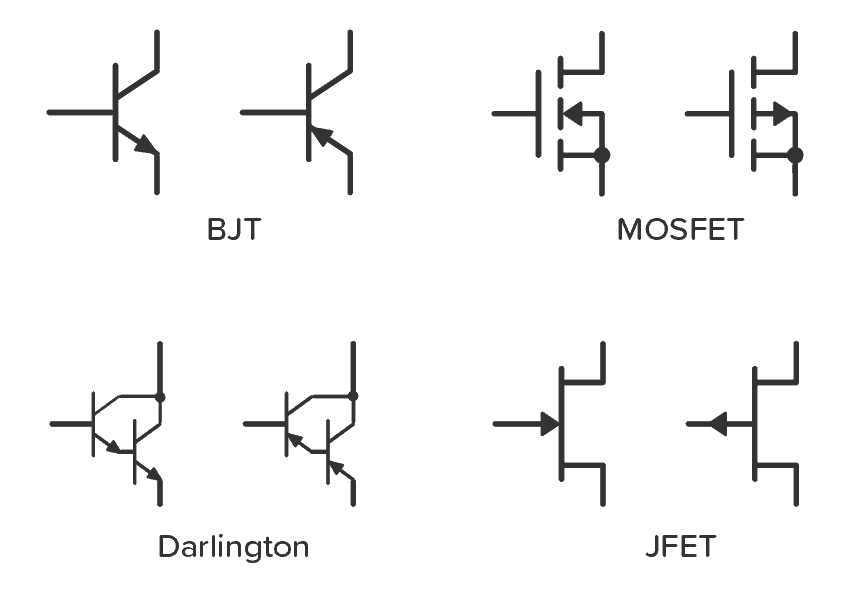
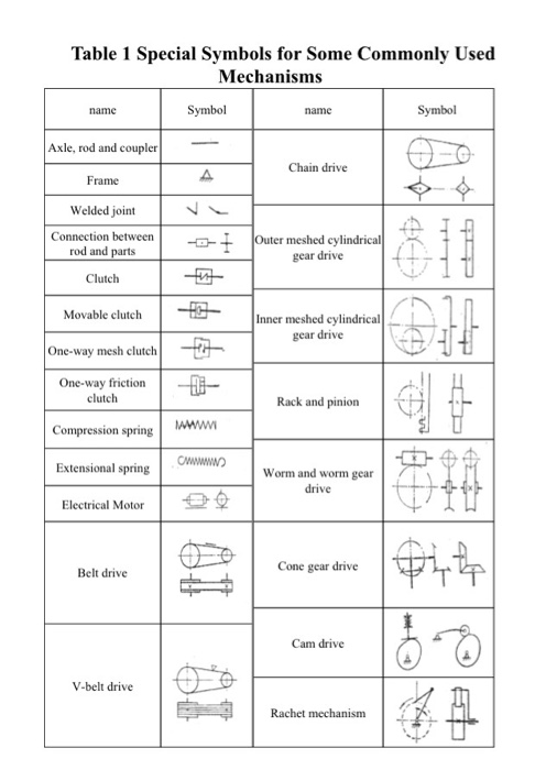
Schematics using international symbols may instead use a featureless rectangle, instead of the squiggles. Electrical circuit schematic symbols are graphical sign, that is used to design electronic, electrical circuit schematic diagram. Mechanical drawing symbols | mechanical engineering. It reveals the components of the circuit as simplified forms and also the power as well as signal links between the devices. Our circuit diagram symbol library is schematic and includes many icons commonly used by engineers. Electrical symbols and electronic circuit symbols are used for drawing schematic diagram. • isnninogrmmleoaplsloytleospsceihnngeslemwtihatcrthoiwcs, the resistors are all of the same wattage and this will be stated somewhere on the schematic. As you go through various parallax microcontroller tutorials, you will see schematics describing the circuits to be built. Circuit symbols overview resistors capacitors inductors, coils, chokes & transformers diodes schematic symbols are used to represent different electronic components and devices in circuit diagrams from wires to batteries and passive components to. The symbols represent electrical and electronic components. A schematic diagram is a drawing of the circuit, with wires represented by lines and special symbols used for the various electronic components. The simple crossing on the left is correct but may be misread as a join where the 'blob' has been. Click on each link given below to view the symbols.
01_b_r03 electrical basics drawing index. In this learning activity you'll review various types of common components used in electronics and view their schematic diagram symbols. In complex diagrams it is often necessary to draw wires crossing even though they are not connected. Electrical symbols and electronic circuit symbols are used for drawing schematic diagram. Also seen dependcin?g upon the cocu?ntry of origin.
Schematic Symbols The Essential Symbols You Should Know from www.build-electronic-circuits.com Complete circuit symbols of electronic components. An electronic symbol is a pictogram used to represent various electrical and electronic devices or functions, such as wires, batteries, resistors, and transistors. Basics 8 aov elementary block diagram. Create electrical circuit diagrams and schematics with electrical symbols provided by smartdraw software. To read and interpret electrical diagrams and schematics, the basic symbols and conventions used in the drawing must be understood. It can be used for a zero potential reference point from where current is measured. Circuit layouts and schematic diagrams are a simple and effective way of showing pictorially the electrical. Some circuit symbols used in schematic diagrams are shown below.
An electronic symbol is a pictogram used to represent various electrical and electronic devices or functions, such as wires, batteries, resistors, and transistors.
01_b_r03 electrical basics drawing index. Circuit symbols are used in circuit diagrams (schematics) to represent electronic components. Don't know or know a bit about schematic symbols. Create electrical circuit diagrams and schematics with electrical symbols provided by smartdraw software. The symbols represent electrical and electronic components. There is a quite adequate collection of symbol for electrical, electronic circuit. Standard electrical jic / nfpa symbols used to represent contactors, thermal overloads, motors and transformers for usage in electrical schematic diagrams. Click on each link given below to view the symbols. Electrical symbols are the most commonly used symbols in circuit diagramming. It reveals the components of the circuit as simplified forms and also the power as well as signal links between the devices. Start studying schematic diagrams symbols. A single cell or other power source is represented by a long and a short parallel these circuit symbols will be frequently used throughout the remainder of lesson 4 as electric circuits are represented by schematic diagrams. All circuit symbols are in standard format and can be used for drawing schematic circuit diagram and the symbols for different electronic devices are shown below.
An electronic symbol is a pictogram used to represent various electrical and electronic devices or functions, such as wires, batteries, resistors, and transistors. Create electrical circuit diagrams and schematics with electrical symbols provided by smartdraw software. The basic building blocks of schematic diagrams use a set of standardized symbols to represent different component types. There are two different symbols used, either a zigzag line, or a rectangle. We are very happy to help you to get information regarding electrical schematic diagram symbols, when you found the picture vagueness in electrical.
Solved Experiment One Drawing Of Kinematic Diagram Of Me Chegg Com from media.cheggcdn.com Mechanical drawing symbols | mechanical engineering. Circuit symbols overview resistors capacitors inductors, coils, chokes & transformers diodes schematic symbols are used to represent different electronic components and devices in circuit diagrams from wires to batteries and passive components to. Complete circuit symbols of electronic components. Below is a list of common symbols you might see in these schematics. Electrical symbols are used to represent electrical and electronic devices in schematic diagrams. Schematics using international symbols may instead use a featureless rectangle, instead of the squiggles. Don't know or know a bit about schematic symbols. Learn vocabulary, terms and more with flashcards, games and other study tools.
Start studying schematic diagrams symbols.
Electrical symbols are the most commonly used symbols in circuit diagramming. Learn vocabulary, terms and more with flashcards, games and other study tools. The simple crossing on the left is correct but may be misread as a join where the 'blob' has been. As nowadays there is no single standard, most of the schematic symbols shown here, are represented in the main international standards. > edraw symbol > electrical symbols for electrical diagrams. Circuit symbols are used in circuit diagrams (schematics) to represent electronic components. To read and interpret electrical diagrams and schematics, the basic symbols and conventions used in the drawing must be understood. Mechanical drawing symbols | mechanical engineering. It reveals the components of the circuit as simplified forms and also the power as well as signal links between the devices. Click on each link given below to view the symbols. In complex diagrams it is often necessary to draw wires crossing even though they are not connected. There is a quite adequate collection of symbol for electrical, electronic circuit. Apart from the circuit symbols.