Home
› Wiring Diagram For Trailers : Trailer Wiring Diagrams | North Texas Trailers | Fort Worth - In power design, a wabco trailer abs wiring diagram is normally applied.
Wiring Diagram For Trailers : Trailer Wiring Diagrams | North Texas Trailers | Fort Worth - In power design, a wabco trailer abs wiring diagram is normally applied.
Wiring Diagram For Trailers : Trailer Wiring Diagrams | North Texas Trailers | Fort Worth - In power design, a wabco trailer abs wiring diagram is normally applied.. Wiring plug diagram created date: A wiring diagram usually gives information nearly the relative twist and pact of devices and terminals on the devices, to encourage in building or servicing the device. The electrics are required to power the lights on your trailer and, if you own a caravan, the internal electrics inside the caravan, therefore it is. Are now using 5 wire flat plug wiring to be more compatible with 4 and 5 wire vehicles. You must check the trailer manual to see if the wiring is correct, but normally the white wire is called the ground wire, while the brown wire is used for tail lights.
To read the wiring diagram, first, you should know what basic elements are included in the wiring diagram, and what picture icons are used to indicate them. Each part should be placed and linked to different parts in specific way. Basically, this is a way of applying the trailer brakes if the trailer comes disconnected from the tow vehicle. It is very easy to attract a wiring diagram; Common elements in the wiring diagram are ground, power supply, wire and connection, output devices, switches, resistors, logic gates, lights, etc.
Trailer Light Wiring Diagram from www.championtrailers.com The safety and security of all individuals on or off the road, as well as those operating a mechanized lorry, depends on. Common elements in the wiring diagram are ground, power supply, wire and connection, output devices, switches, resistors, logic gates, lights, etc. Above we have describes the main types of trailer wiring diagrams. If your vehicle is not equipped with a working trailer wiring harness, there are a number of different solutions to provide the perfect fit for. 7 way plug wiring diagram standard wiring* post purpose wire color tm park light green (+) battery feed black rt right turn/brake light brown lt left turn/brake light red s trailer electric brakes blue gd ground white a accessory yellow this is the most common (standard) wiring scheme for rv plugs and the one used by major auto manufacturers today. Just like just about anything, common servicing checks will help in averting some major troubles. Trailer wiring diagrams trailer wiring connectors various connectors are available from four to seven pins that allow for the transfer of power for the lighting as well as auxiliary functions such as an electric trailer brake controller, backup lights, or a 12v power supply for a winch or interior 5 flat trailer wiring harness 40 2018 loadritetrailer the hull plug diagram load trail llc 4 way 22 18 lights brakes rule pumps full 280z diagrams etrailer com parts catalog rite trailers inc and installation cadillac electrical abs installing pin chevy speakers connector pinout operator s manual how to install.
Many trailers are required to have a breakaway system on board.
Trailer side car side wiring plug diagram. 5 wire trailer plug wiring diagram 12 clever 12s wiring diagram caravan references with images. Trailer wiring diagrams trailer wiring connectors various connectors are available from four to seven pins that allow for the transfer of power for the lighting as well as auxiliary functions such as an electric trailer brake controller, backup lights, or a 12v power supply for a winch or interior trailer lights. This guide will be talking trailer wiring diagram 5 way.which are the advantages of understanding such understanding? Basically, this is a way of applying the trailer brakes if the trailer comes disconnected from the tow vehicle. Above we have describes the main types of trailer wiring diagrams. But, it does not have as sophisticated and electric consuming characteristics that rv and other expensive trailers may have. We also use all red lights on all trailers except for the zephyr, blade and xl models. To connect the electric system of your trailer to the vehicle, you will be using special connector. 7 way plug wiring diagram standard wiring* post purpose wire color tm park light green (+) battery feed black rt right turn/brake light brown lt left turn/brake light red s trailer electric brakes blue gd ground white a accessory yellow this is the most common (standard) wiring scheme for rv plugs and the one used by major auto manufacturers today. A wiring diagram usually gives information nearly the relative twist and pact of devices and terminals on the devices, to encourage in building or servicing the device. Trailer wiring diagrams one of the most important parts of fitting a towbar to your vehicle is connecting the electrics from the towing vehicle to the trailer or caravan that you are towing. As a professional rv transporter i have seen to many trucks wired with those 2 wires to small and cause a fire from overheating.
Start by cutting the white wire and attaching it to the trailer frame. In many parts of the usa, trailers over 3000 lbs gvwr need a breakaway kit, so check your local laws. As a professional rv transporter i have seen to many trucks wired with those 2 wires to small and cause a fire from overheating. We also use all red lights on all trailers except for the zephyr, blade and xl models. Trailer side car side wiring plug diagram.
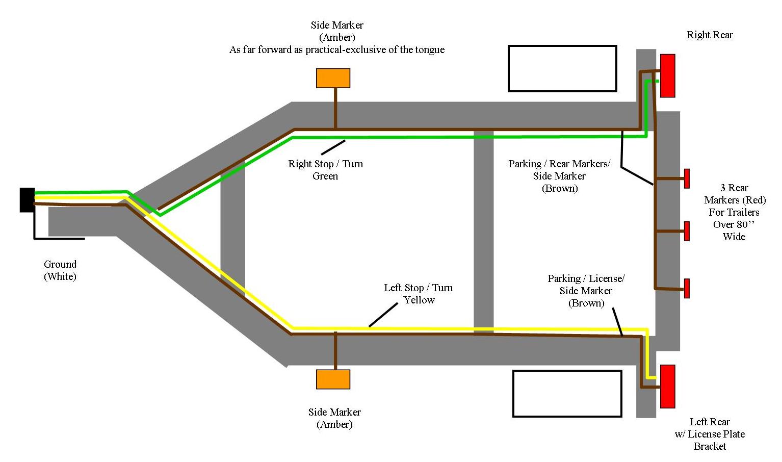
7 Pin Round Trailer Wiring Diagram Australia | Trailer Wiring Diagram from trailer-wiring-diagram.com Trailer wiring diagrams trailer wiring connectors various connectors are available from four to seven pins that allow for the transfer of power for the lighting as well as auxiliary functions such as an electric trailer brake controller, backup lights, or a 12v power supply for a winch or interior trailer lights. But, it does not have as sophisticated and electric consuming characteristics that rv and other expensive trailers may have. Just like just about anything, common servicing checks will help in averting some major troubles. You must check the trailer manual to see if the wiring is correct, but normally the white wire is called the ground wire, while the brown wire is used for tail lights. Above we have describes the main types of trailer wiring diagrams. Yellow and green are for left and right turns and braking. Common elements in the wiring diagram are ground, power supply, wire and connection, output devices, switches, resistors, logic gates, lights, etc. You simply require to have a excellent understanding on various types of wiring and their purposes.
Right turn signal / stop light (green), left turn signal / stop light (yellow), taillight / license / side marker (brown) and a ground (white).
In power design, a wabco trailer abs wiring diagram is normally applied. To connect the electric system of your trailer to the vehicle, you will be using special connector. As a professional rv transporter i have seen to many trucks wired with those 2 wires to small and cause a fire from overheating. Bike to trailer wiring diagram the wiring schematic that we use is: The wiring diagram is normally made use of in electrical design to plan the positioning of electrical circuits. Are now using 5 wire flat plug wiring to be more compatible with 4 and 5 wire vehicles. The safety and security of all individuals on or off the road, as well as those operating a mechanized lorry, depends on. 4 way flat molded connectors allow basic hookup for three lighting functions; 7 way plug wiring diagram standard wiring* post purpose wire color tm park light green (+) battery feed black rt right turn/brake light brown lt left turn/brake light red s trailer electric brakes blue gd ground white a accessory yellow this is the most common (standard) wiring scheme for rv plugs and the one used by major auto manufacturers today. Many trailers are required to have a breakaway system on board. The electrics are required to power the lights on your trailer and, if you own a caravan, the internal electrics inside the caravan, therefore it is. Yellow and green are for left and right turns and braking. When shopping for trailer connectors remember that the male end is mounted on the vehicle side and the female on the trailer side.
4 way flat molded connectors allow basic hookup for three lighting functions; Trailer wiring diagrams trailer wiring connectors various connectors are available from four to seven pins that allow for the transfer of power for the lighting as well as auxiliary functions such as an electric trailer brake controller, backup lights, or a 12v power supply for a winch or interior Otherwise, the arrangement won't work as it ought to be. Below is the generic schematic of how the wiring goes. In many parts of the usa, trailers over 3000 lbs gvwr need a breakaway kit, so check your local laws.
Jayco Trailer Wiring Diagram | Trailer Wiring Diagram from trailer-wiring-diagram.com Start by cutting the white wire and attaching it to the trailer frame. 5 wire trailer plug wiring diagram 12 clever 12s wiring diagram caravan references with images. Trailer wiring diagrams trailer wiring connectors various connectors are available from four to seven pins that allow for the transfer of power for the lighting as well as auxiliary functions such as an electric trailer brake controller, backup lights, or a 12v power supply for a winch or interior 5 flat trailer wiring harness 40 2018 loadritetrailer the hull plug diagram load trail llc 4 way 22 18 lights brakes rule pumps full 280z diagrams etrailer com parts catalog rite trailers inc and installation cadillac electrical abs installing pin chevy speakers connector pinout operator s manual how to install. Trailer side car side wiring plug diagram. Trailer wiring diagrams 4 way systems. Wiring plug diagram created date: Many trailers are required to have a breakaway system on board.
Many trailers are required to have a breakaway system on board.
Right turn signal / stop light (green), left turn signal / stop light (yellow), taillight / license / side marker (brown) and a ground (white). Trailer side car side wiring plug diagram. The wiring diagram is normally made use of in electrical design to plan the positioning of electrical circuits. Trailer wiring diagrams trailer wiring connectors various connectors are available from four to seven pins that allow for the transfer of power for the lighting as well as auxiliary functions such as an electric trailer brake controller, backup lights, or a 12v power supply for a winch or interior trailer lights. If your vehicle is not equipped with a working trailer wiring harness, there are a number of different solutions to provide the perfect fit for. Each part should be placed and linked to different parts in specific way. To connect the electric system of your trailer to the vehicle, you will be using special connector. The safety and security of all individuals on or off the road, as well as those operating a mechanized lorry, depends on. Wiring plug diagram created date: In power design, a wabco trailer abs wiring diagram is normally applied. We also use all red lights on all trailers except for the zephyr, blade and xl models. Many trailers are required to have a breakaway system on board. You simply require to have a excellent understanding on various types of wiring and their purposes.